Vacuum Pump Maintenance Checklist for Industrial Applications
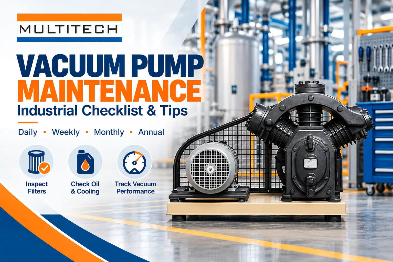
Effective vacuum pump maintenance is condition-based, model-specific and tied to the process. Operators should record vacuum level, pump-down time, temperature, current, noise, vibration, oil condition where applicable, filter restriction and cooling status against a stable baseline. The maintenance plan must distinguish dry pumps from oil-sealed rotary vane pumps because their service items, contamination risks and shutdown methods differ.
A checklist is valuable only when it defines frequency, acceptance criteria, safe isolation, responsible person and the action required after an abnormal result. Gasair MultiTech offers both dry vacuum pumps and oil-sealed rotary vane vacuum pumps. Always apply the supplied model manual, process hazard assessment and site lockout procedure before opening, draining or testing equipment.
Why Vacuum Pump Maintenance Must Match the Process
The pump handles whatever reaches its inlet: clean dry air, moisture, solvents, dust, product carryover or corrosive vapor. Two identical pumps may therefore need different inspection intervals. Packaging, pharmaceutical, chemical, plastics and central-vacuum duties impose different contamination, duty-cycle and vacuum-stability demands.
Start by documenting gas composition, expected condensate, operating hours, inlet pressure range, number of starts, ambient temperature and cleaning cycles. Review whether separators, traps, scrubbers or inlet filters are working. Treat process changes as maintenance changes; a new solvent, powder or wash cycle can invalidate the former service interval.
Daily or Shift Checklist
| Check | Normal evidence | Escalate when |
|---|---|---|
| Vacuum level | Stable against the same operating condition | Setpoint is missed or recovery slows |
| Pump sound | Consistent mechanical sound | Knock, scrape, squeal or sudden tone change |
| Temperature | Within established trend and manual limit | Rapid rise or repeated high-temperature alarm |
| Leaks | No visible oil, water or process leak | Fresh leak, mist or pooling appears |
| Cooling | Air path or water flow unobstructed | Fan, flow or heat rejection is impaired |
| Oil where fitted | Correct level and normal appearance | Low, dark, emulsified or contaminated oil |
| Alarms | No unexplained active or repeated alarms | Trip, interlock bypass or communication loss |
Record readings while the pump is in a comparable state. Vacuum and motor current during idle cannot be compared directly with values under process load. Operators should note the product, batch or machine state so the trend remains meaningful. If the pump sounds abnormal or has a safety-related leak, follow the approved stop-and-isolate procedure instead of continuing to collect data.
Weekly Inspection Tasks
- Inspect inlet filters, traps and separators for restriction or carryover.
- Check guards, anchors, flexible connectors and accessible pipe supports.
- Clean cooling-air inlets and confirm hot discharge air is not recirculating.
- Inspect hoses, flanges and valves for physical damage or leak evidence.
- Drain condensate from approved points using the required containment method.
- Review alarms, pump-down time and operating-hour trends for deterioration.
- Confirm duty and standby pumps change over as intended where redundancy exists.
A weekly walk-round should include the process side, not just the pump skid. A stuck valve, collapsed hose or blocked trap can appear as a pump problem. Verify that temporary hoses, closed isolation valves or recent maintenance have not changed the flow path. Photograph developing leaks or contamination so the next review can assess whether they are growing.
Monthly Condition Review
Compare operating vacuum, pump-down time, motor current, temperature and maintenance events with the commissioning baseline. Review differential pressure across filters if instruments are installed. Trend review is more useful than isolated values because gradual restriction, wear or leakage may remain within alarm limits while performance steadily worsens.
Inspect accessible electrical terminals, cable glands and control-panel ventilation under the site’s safe electrical procedure. Check that sensors are secure and readings are plausible. Test standby automatic start and alarm communication without compromising the process. Confirm that bypasses introduced during troubleshooting have been removed and documented.
Oil-Sealed Rotary Vane Pump Maintenance
Oil in a rotary vane pump lubricates, seals and carries heat, so its condition directly affects performance. Check level under the manufacturer’s stated operating condition; overfilling can cause carryover and underfilling can damage the pump. Observe color, odor, suspended material, foaming and signs of water. Do not top up different oils unless compatibility is confirmed.
Set oil-change intervals using the manual and actual contamination. Harsh vapors or frequent moisture ingestion may require shorter intervals than clean service. Replace oil filters, exhaust-mist elements and seals at approved intervals or condition thresholds. Gas ballast, if fitted, must be used according to the process and supplier guidance; it can help manage condensable vapor but may change attainable vacuum and exhaust behavior.
Safe oil handling
Allow the pump to reach the specified safe condition, isolate energy and prevent restart. Use compatible containers, control spills and dispose of used oil according to site and legal requirements. Record oil type, quantity, hours, reason for change and observations. Unusual metal, water or solvent contamination should trigger root-cause review rather than only another refill.
Dry Vacuum Pump Maintenance
A dry pump has no sealing fluid in the compression chamber, but it is not maintenance-free. External bearings, gears, seals, purge systems, cooling circuits and filters may still require service. Check for deposits or process carryover that can narrow clearances, create imbalance or cause seizure. Purge and shutdown sequences are especially important for condensable or reactive gases.
Follow the manufacturer’s cleaning method; aggressive flushing or incorrect solvents can damage coatings, seals or downstream treatment. Review gear oil or bearing lubrication where the design uses it, while keeping the process chamber distinction clear. The dry vacuum pump product page emphasizes application-dependent configuration, so maintenance scope should be finalized from the exact pump and gas service.
Inspect Filters, Traps and Separators
An inlet filter protects the pump but adds pressure loss when restricted. Use differential pressure or a documented inspection interval rather than waiting for visible collapse. Traps and separators must be drained, cleaned and checked for the expected captured material. If a trap suddenly stays empty, verify that it is not bypassed or blocked.
Exhaust filters on oil-sealed pumps control mist and backpressure. A saturated element can increase discharge pressure and temperature. Use the correct element, seals and installation orientation. MultiTech also lists compressed-air filtration products those products should not be assumed interchangeable with vacuum inlet or exhaust components unless specifically approved.
Check Cooling and Ventilation
Heat accelerates oil degradation, reduces seal life and can cause trips. Keep air-cooled surfaces and fan inlets clean and preserve the specified clearance around the pump. Verify fan direction and operation after electrical work. Prevent discharge air from recirculating into the inlet side of the skid or room.
For water-cooled pumps, check flow, inlet temperature, pressure, strainers, leaks and water quality. Loss of cooling may not immediately stop production but can shorten component life. Any scale, corrosion or repeated high-temperature alarm requires investigation of the cooling circuit and process load together.
Find Leaks Systematically
A vacuum leak increases pump load and pump-down time and can introduce moisture or oxygen into the process. Begin with recent work, flexible connections, valve stems, instrument ports, gaskets and access covers. Isolate sections where the system design permits and use an approved leak-test method compatible with the process.
Do not assume the pump is worn because vacuum is low. Confirm gauge accuracy, valve position, process gas load, filter restriction and piping integrity first. Likewise, a strong ultimate vacuum test does not prove adequate flow under production conditions. Diagnose with both pressure and time or flow behavior.
Use Performance Trending to Set Service Intervals
| Trend | Possible interpretation | Next check |
|---|---|---|
| Longer pump-down time | Leak, restriction, wear or higher gas load | Isolate system sections and verify process state |
| Rising motor current | Mechanical drag, pressure change or deposit | Check temperature, inlet and drive condition |
| Higher temperature | Cooling loss, overload or oil issue | Inspect airflow/water and oil condition |
| Worsening vacuum | Leak, contamination, valve or wear | Verify gauge, valves, filters and pump |
| Oil carryover | Overfill, separator restriction or gas load | Check level, element and operating point |
| More vibration | Alignment, bearing, deposit or mounting issue | Inspect foundation and arrange condition check |
Define alert and action limits from supplier guidance plus a healthy baseline. One abnormal data point may be a measurement problem; a consistent trend needs action. Retain instrument identity and calibration status. When a pump is overhauled, establish a new baseline and compare it with the original acceptance result.
Quarterly and Annual Planned Maintenance
Planned intervals should combine calendar time, operating hours, starts and process severity. Typical scope may include filter replacement, oil and separator service, belt or coupling inspection, seal review, cooling-system cleaning, valve inspection, electrical checks, instrument verification and standby testing. Only include tasks applicable to the installed design.
Annual work is also an opportunity to inspect the receiver, piping supports, isolation valves, exhaust route and safety devices under applicable site procedures. Review spare holdings, obsolete parts and service response. MultiTech describes AMC/CAMC and after-sales support on its About Us page a contract should state exact model coverage, consumables, response, exclusions and report deliverables.
Prepare for a Safe Shutdown and Restart
- Notify operations and place the process in the approved safe state.
- Isolate electrical, pneumatic, hydraulic, thermal and process energy sources.
- Allow temperature and pressure to reach the specified service condition.
- Prevent hazardous material entry and apply purge or decontamination steps.
- Verify zero-energy state using the site lockout procedure.
- Complete maintenance with correct parts, torque, fluids and cleanliness controls.
- Remove tools, restore guards, check rotation or settings and restart under observation.
- Record readings and compare the returned pump with its baseline.
Spare Parts and Service Records
Maintain model and serial numbers, exploded parts information, oil specification, filter elements, seals, belts or couplings, sensors and critical lead times. Store elastomers and lubricants within supplier shelf-life and environmental requirements. Avoid visually similar substitutes whose material, filtration or pressure rating is unverified.
Each work order should capture symptom, readings, diagnosis, parts, labor, settings, contamination observations and post-service test. Good records reveal repeated causes and allow maintenance frequency to be justified. They also help a service partner arrive with the correct parts. For technical support, use MultiTech’s Contact Us page and provide the pump identity and duty details.
Common Maintenance Mistakes
- Applying one fixed interval to every gas service and duty cycle.
- Changing oil without investigating water, solvent or particulate contamination.
- Cleaning a dry pump with an unapproved liquid or method.
- Replacing filters without recording restriction or root cause.
- Comparing readings taken under different process conditions.
- Operating around a failed alarm, high temperature or safety interlock.
- Restarting after service without checking valves, rotation, guards and baseline performance.
A Practical Maintenance Frequency Matrix
| Frequency | Core activities | Owner |
|---|---|---|
| Each shift | Readings, sound, leaks, cooling, alarms and oil level | Operator |
| Weekly | Filters, traps, connectors, guards, drains and standby readiness | Operator/maintenance |
| Monthly | Trend review, controls, electrical enclosure and alarm tests | Maintenance engineer |
| Quarterly or hours-based | Applicable oil, filters, belts, seals and cooling service | Qualified technician |
| Annual or major shutdown | Detailed inspection, instruments, piping, safety and performance baseline | Service team/plant engineering |
This matrix is a planning framework, not a replacement for the pump manual. Shorten or lengthen intervals only through an approved reliability review using process exposure, condition data and supplier requirements. Safety-critical checks should not be deferred because recent production demand was low.
Root-Cause Review After a Failure or Repeated Alarm
Restore production safely, but do not stop the investigation at the failed part. Preserve alarm history, trends, oil or deposit samples where appropriate, damaged components and operator observations. Establish the sequence of events: process change, loss of cooling, blocked inlet, liquid carryover, power disturbance, control response and final trip. Compare the evidence with maintenance and service records.
The corrective action may involve process controls, traps, ventilation, operating procedure or training rather than only pump repair. Define how effectiveness will be verified—such as stable temperature, reduced contamination or restored pump-down time—and review the result after enough operating hours. Repeated replacement without causal evidence can conceal a system problem and consume spares.
Maintenance Controls for Hazardous Process Gases
Where the pump handles toxic, flammable, corrosive, oxygen-enriched, biologically active or otherwise hazardous material, use the site hazard assessment and specialist procedures. Isolation alone may not make the pump safe to open. Purging, decontamination, gas testing, residue handling, ventilation, permits and specific PPE may be necessary. Identify retained volumes in separators, oil and dead legs.
Tell external service personnel the actual process exposure before equipment is shipped or opened. Use a contamination declaration and approved packaging. Do not use compressed air, solvents or heat for cleaning unless the method is authorized for both the pump and material. Verify the exhaust treatment and safe discharge path before restart.
Reliability Metrics for the Vacuum System
Track availability, failures, mean repair time, emergency callouts, pump-down time, energy or current trend, oil and filter consumption and repeated alarm categories. Separate pump-caused downtime from process, valve, piping, instrument and utility causes. This prevents purchasing decisions from being based on an inaccurate failure label.
Use the data to decide whether a standby unit, automatic changeover, additional trapping, monitoring or redesign is justified. Reliability targets should reflect production consequence and product risk. A redundant pump does not provide resilience if both units share one blocked inlet, cooling failure, electrical supply or untested control sequence.
Audit the Maintenance Program Annually
- Compare planned tasks with completed work and overdue safety-critical items.
- Review whether intervals match contamination, hours, starts and failure history.
- Confirm manuals, drawings, lockout steps and emergency contacts remain current.
- Test availability of critical spares, approved oil and competent service support.
- Check that instruments used for condition decisions are identified and verified.
- Close recurring defects with engineering actions rather than repeated temporary repairs.
Frequently Asked Questions
1. How often should a vacuum pump be serviced?
Use the manufacturer’s calendar or operating-hour interval adjusted for duty and contamination. Daily checks and trend review continue between major services.
2. What readings should operators record?
Record operating vacuum, pump-down time where practical, temperature, motor current, oil condition, alarms, noise and the process state.
3. Why has pump-down time increased?
Possible causes include leaks, blocked filters, valve position, higher gas load, contamination or pump wear. Check the system before assuming one cause.
4. Can any oil be used in an oil-sealed vacuum pump?
No. Use the approved type and viscosity for the model and process; incompatible oil can affect sealing, lubrication and chemical resistance.
5. Do dry vacuum pumps need maintenance?
Yes. Bearings, gears, seals, purges, cooling and process deposits still require inspection and model-specific service.
6. When should an inlet filter be replaced?
Use differential pressure, condition and the approved interval. A restricted filter can reduce effective pumping speed.
7. What causes vacuum-pump overheating?
Common causes include poor ventilation, cooling failure, excessive gas load, restriction, oil problems or internal wear.
8. How can a vacuum leak be found?
Verify instruments and valves, inspect recent work, isolate sections where permitted and use a process-compatible approved leak-test method.
9. What does milky vacuum-pump oil indicate?
It often suggests moisture contamination or emulsification. Identify the ingress or condensation cause before returning the pump to normal duty.
10. Should standby pumps be run periodically?
Yes, under the site and supplier procedure, so automatic changeover, lubrication, alarms and readiness are demonstrated.
11. What information should be sent to a service provider?
Send model, serial number, hours, gas service, symptoms, readings, alarms, photos, service history and required shutdown window.
12. What must be checked after maintenance?
Verify guards, valves, fluids, rotation where applicable, leaks, settings, alarms, temperature, vacuum and performance against baseline.
Use Maintenance Data to Protect Vacuum Reliability
The most effective vacuum pump maintenance program combines disciplined shift checks, condition trends, process awareness and model-specific service. Build the checklist around the installed pump, gas stream and production consequence, then close every abnormal finding with evidence. Review MultiTech’s vacuum pump range, learn about the team on the About Us page, and use the official contact page to discuss spares, service scope or a pump-specific maintenance plan.





-
Liquid Ring Vacuum Pump: Applications and Selection Factors
-
Vacuum Pump Price in India: Complete Buying Guide
-
Ammonia Cracker Unit: Working Principle and Industrial Applications
-

Air Compressors for Automotive Manufacturing Capacity and Selection Guide
-

Nitrogen Generator for Food Packaging: Purity and Capacity Requirements


