Air Compressors for Automotive Manufacturing Capacity and Selection Guide

An air compressor for automotive manufacturing should be selected from measured demand at the required point-of-use pressure, not from connected tool ratings alone. The system must support production peaks, robot and actuator duty, paint or finishing air-quality requirements, leakage, maintenance and future changes without spending excessive energy on unnecessary pressure. Compressor type, treatment, receivers, piping and controls should be evaluated as one system.
A dependable plant normally separates truly critical demand from intermittent demand, identifies the lowest pressure each process needs and defines what must continue during maintenance. The right answer may be one base-load compressor plus a trim machine, multiple sequenced units or dedicated systems for different air qualities. A single oversized compressor can cycle or unload inefficiently and still fail during a short peak.
MultiTech lists rotary screw air compressors, reciprocating piston compressors, compressed air filters and drying equipment. Buyers should share the demand profile, pressure, air-quality target and site conditions before seeking a model recommendation.
Where Compressed Air Is Used in Automotive Manufacturing
| Application | Demand characteristic | Selection concern |
|---|---|---|
| Assembly tools | Intermittent with shift peaks | Pressure stability and local drops |
| Pneumatic cylinders and grippers | Fast repeated cycles | Peak flow and response |
| Body shop automation | Sequenced and safety-critical | Reliability and clean distribution |
| Painting and finishing | Sensitive to moisture or contamination | Air treatment and segregation |
| Tyre and leak testing | Defined test pressure and accuracy | Stable regulated supply |
| Cleaning and blow-off | Often variable and waste-prone | Safe nozzles and demand control |
The same plant can contain processes with very different requirements. Combining them at one high pressure may simplify piping but raise energy use and treatment cost. A pressure or air-quality zone can be justified where one process would otherwise force the entire plant to operate at a more demanding condition.
Build a Measured Demand Profile
Start with flow and pressure logging over representative production shifts, including start-up, breaks, product changes and planned maintenance. Record compressor power, loaded and unloaded operation, header pressure, dew point where relevant and major machine states. Connected capacity is useful for inventory, but diversity and duty cycle determine actual demand.
Separate current demand, known projects and speculative expansion. State leakage as a measured or testable value rather than hiding it in a large safety factor. If production is not yet operating, build a bottom-up equipment schedule and require machine vendors to provide normal, peak and minimum inlet requirements.
Normal flow peak flow and starting events
Normal flow establishes the base-load requirement. Short peaks may be handled by receiver storage or a responsive trim compressor if the pressure band permits. Long production peaks require installed compressor capacity. Simultaneous machine start-up after a shutdown can create a special event that should be sequenced rather than solved only by buying more compressor power.
Choose the Lowest Practical System Pressure
Every restriction between the compressor and tool consumes pressure: treatment, piping, valves, hoses, quick couplings and local regulators. The compressor discharge pressure must cover the actual point-of-use requirement plus verified losses, not an arbitrary margin. Raising the whole plant pressure to fix one bad branch often increases leakage and power demand while leaving the restriction unresolved.
Create a pressure map during normal and peak operation. Correct undersized lines, blocked filters, poorly selected couplings and unstable regulators. If one process needs higher pressure, compare a local booster or dedicated supply with raising the common header. Document the agreed minimum pressure at critical machines.
Match Compressor Type to the Duty
| Option | Typical fit | Questions to resolve |
|---|---|---|
| Fixed-speed rotary screw | Stable continuous base demand | Loaded hours, unload power and sequencing |
| Variable-speed rotary screw | Variable trim demand within efficient range | Minimum speed, cooling and control band |
| Reciprocating compressor | Intermittent or smaller duty | Cycle limits, pulsation, noise and maintenance |
| Multiple compressors | Reliability and variable production | Lead-lag logic and common controls |
| Dedicated clean-air unit | Sensitive process isolated from general air | Air quality, redundancy and distribution |
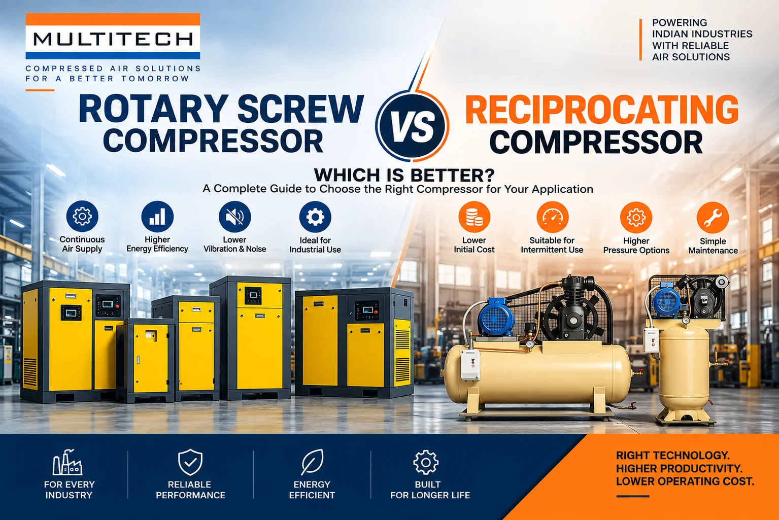
A rotary screw compressor is commonly evaluated for continuous industrial service, while a piston unit may suit intermittent demand. Variable speed can provide efficient trim control when operated within its intended range. No technology is automatically best; compare verified performance at expected ambient conditions and load points.
Review motor starting method, electrical supply, cooling-air path, ventilation, noise, condensate handling, footprint and access. Plant utility rooms often fail because heat is recirculated or service clearances disappear after later equipment is added. Layout should allow filter changes, oil service where applicable, motor work and safe lifting.
Define Air Quality by Process
Moisture, particles and oil can cause valve sticking, finish defects, instrument problems and corrosion. Define the allowable contamination and pressure dew point at the point of use, then design treatment for the inlet environment and flow. Do not assume that one filter or dryer description proves final air quality.
MultiTech offers compressed air filters and heatless desiccant dryer options. For a project, verify rated conditions, pressure drop, drain type, purge demand, monitoring and maintenance. Paint or other sensitive processes may justify segregated piping and additional point-of-use protection.
Plan Receivers and Distribution Together
A wet receiver can buffer compressor operation and support moisture separation before treatment; a dry receiver can stabilise treated-air demand. Location and volume should be calculated from the control strategy, peak duration and permissible pressure change. A receiver cannot compensate indefinitely for inadequate installed capacity.
Use a distribution layout that limits pressure drop and supports isolation, drainage and expansion. Loop mains can improve pressure stability and provide alternate flow paths. Size branches for peak machine demand, not only average flow. Slope and drain arrangements must match the moisture-management strategy, and dead legs should be controlled.
Design for Redundancy and Maintenance
Automotive production can lose substantial output when the air system stops. Define the capacity required with the largest unit unavailable and decide which processes may be curtailed. Redundancy can be full, partial or staged based on business impact. It must include dryers, filters, controls, cooling and electrical supply, not only an idle compressor.
Provide isolation so one machine or treatment train can be maintained safely while the approved load continues. The operating team needs spare parts, service access and an escalation plan. MultiTech describes installation training and after-sales support on its live site; the proposal should state response, exclusions, consumables and planned maintenance for the selected equipment.
Use Controls That Coordinate the Plant
Independent pressure switches can make multiple compressors compete, causing rapid loading, unloading and unstable pressure. A master controller can sequence base and trim machines, rotate operating hours and respond to demand within a narrower band. Control logic should consider minimum run times, unload delays, dryer capacity and the reliability reserve.
Monitoring should trend flow, pressure, power, temperature, dew point, differential pressure and operating states where relevant. Use alarms that lead to an action, not an unmanageable list. Preserve baseline data after commissioning so leakage, filter restriction and control drift can be identified before production is affected.
Estimate Lifecycle Cost Instead of Purchase Price
| Cost area | Include in the comparison |
|---|---|
| Equipment | Compressors, treatment, receivers, controls and installation |
| Energy | Power across actual load profile plus dryer purge and losses |
| Maintenance | Consumables, labour, service and planned downtime |
| Reliability | Standby capacity, spares and production risk |
| Distribution | Piping, pressure drop, drains and future connections |
| Quality | Rejects or process risk from unsuitable air |
Ask suppliers to state flow and power at the same pressure and inlet conditions. Compare specific power at relevant load points, not only motor nameplate. Include unloaded power, cooling fans, purge air and pressure losses. A lower-cost package can become expensive if it operates outside the efficient range or requires the entire system pressure to rise.
Installation and Commissioning Checklist
- Verify foundation, ventilation, intake-air quality, service clearance and lifting route.
- Confirm electrical protection, cable ratings, earthing and motor starting.
- Pressure-test and clean piping using the approved procedure before connection.
- Set drains, separators and condensate handling for actual site conditions.
- Record compressor, dryer, filter and controller settings.
- Test normal, peak, failure, standby and restart operating modes.
- Measure point-of-use pressure and air quality against acceptance criteria.
- Train operators and provide manuals, spares and maintenance schedules.
Common Selection Mistakes
- Adding all tool ratings and applying an arbitrary diversity factor.
- Using excess pressure to overcome bad piping or blocked filters.
- Buying one large unit without a credible maintenance plan.
- Selecting a dryer by nominal flow without temperature and pressure corrections.
- Treating paint-shop air the same as general plant air without verification.
- Ignoring unloaded power, purge loss and pressure drop in energy comparisons.
- Installing equipment where hot discharge air recirculates into the intake.
- Commissioning at light load and never proving production peaks.
A Practical Selection Workflow
- Map processes, air quality, criticality and point-of-use pressure.
- Measure flow, pressure and power through representative production.
- Repair major leaks and restrictions before freezing new capacity.
- Develop base, trim, peak and standby requirements.
- Compare compressor and treatment configurations on the same duty.
- Check room, electrical, cooling, condensate and maintenance interfaces.
- Commission the complete system and retain verified baseline trends.
Information to Send with a Supplier Enquiry
Provide the measured flow profile, minimum point-of-use pressure, air-quality target, ambient conditions, operating hours, shift pattern, current equipment, electrical supply, planned expansion and redundancy expectation. Include a layout or piping sketch and identify sensitive processes. This allows suppliers to price comparable scopes and expose assumptions before purchase.
Review MultiTech’s company background and product pages as a starting point, then require the proposal to identify exact models, rated conditions, accessories, controls, installation responsibilities, tests, warranty and service. Marketing descriptions should not replace a written duty point.
Audit Demand at Machine and Area Level
A plant-wide flow meter shows the total profile but not where demand originates. Temporary sub-metering or controlled isolation can identify body shop, assembly, paint, utilities and maintenance consumption. Compare production and non-production periods to estimate leakage and unmanaged uses. Repeat the audit after changes so savings are verified rather than assumed.
Machine-level observations also expose pressure requirements that have drifted upward over time. Record regulator settings, hose and coupling sizes, blow-off methods and cycle frequency. Where an air use is continuous, compare an electric blower or mechanical method. Any change must preserve process quality and machine warranty.
Plan the Compressor Room as a Maintainable Utility
Lay out equipment in the direction of service flow, but keep enough clearance for coolers, motors, separators, filters and dryer components to be removed. Route hot air outdoors without creating excessive duct resistance and provide clean replacement air. Consider noise, vibration, floor drainage, lighting, lifting points and safe access around rotating and hot surfaces.
Condensate can contain oil or other contaminants depending on compressor and process conditions. Define separation, collection and disposal rather than piping every drain to the nearest floor outlet. Test automatic drains during commissioning and include them in preventive maintenance because a failed drain can waste air or carry water downstream.
Manage Changes After the System Is Commissioned
New robots, tools and production lines should pass through a utility-capacity review before connection. Update the demand model, branch sizing, treatment load and control setpoints. A series of small unrecorded additions can consume the reliability reserve and push a dryer or filter beyond its rated condition before the compressor reaches full load.
Protect the baseline by storing current drawings, equipment settings, controller logic, service records and trend definitions. When pressure is increased or sequencing is changed, record the reason and compare energy and production performance. Revert changes that do not deliver the intended benefit.
Verify Performance During Production
A useful acceptance test combines equipment checks with a production observation. Confirm that header pressure remains within the agreed band while representative tools, cylinders and robots operate. Record compressor power and state, dryer condition, filter differential pressure and pressure at critical points. The test should identify whether storage and trim response handle short peaks without unnecessary pressure escalation.
Where full production cannot be witnessed, agree a post-start-up verification period and a method for correcting capacity or control gaps. Trend at least the signals needed to separate excessive demand, distribution loss, treatment restriction and compressor-control behaviour. A single pressure reading at the compressor room is not sufficient evidence of plant performance.
Prevent Leaks from Returning
Leak repair should be a recurring programme with tagging, prioritisation, verification and reporting. Survey during non-production periods where possible and measure the change in base flow after repairs. Assign responsibility for fixing hose, valve, coupling and drain leaks, and make leak-resistant connection practices part of new-equipment standards.
Review compressed-air performance alongside production volume so a lower flow is not mistaken for an efficiency gain during a slow shift. Useful indicators include energy per unit of compressed air, energy per production unit, leak flow, pressure stability and time spent unloaded. The plant should define consistent boundaries and meter quality before using these values for supplier acceptance or internal targets.
Seasonal temperature and humidity can change compressor cooling, dryer loading and condensate volume. Recheck treatment and ventilation during demanding weather rather than relying only on a mild-day commissioning test. Trend deviations against ambient conditions before concluding that equipment capacity has changed.
Include production, maintenance and utility teams in the final review so operating changes are practical, owned and reflected in shift procedures.
Frequently Asked Questions
1. What compressor is commonly used in automotive manufacturing?
Rotary screw compressors are often evaluated for continuous demand, while reciprocating units can suit intermittent duty. The correct choice depends on the measured load profile.
2. How should compressor capacity be calculated?
Use measured or engineered normal flow, sustained peak flow, pressure, air quality, leakage, future demand and the required capacity during maintenance.
3. Should connected tool demand be added directly?
No. Tool ratings need duty cycle and simultaneity analysis. Logging an operating plant provides better evidence.
4. Why is point-of-use pressure important?
It reveals losses through dryers, filters, piping and couplings. Compressor discharge pressure alone can hide a weak distribution system.
5. Is a variable-speed compressor always more efficient?
No. It performs best when the variable demand falls within its efficient control range and the base-load arrangement is correct.
6. What air treatment is required for painting?
The project must define moisture, particle and oil limits at the application, then select and verify treatment and distribution accordingly.
7. How much receiver capacity is needed?
Receiver sizing depends on peak flow, duration, compressor control, pressure band and where storage is located. It requires a project calculation.
8. What redundancy is appropriate?
It depends on production loss risk and allowable curtailment. Assess the system with the largest required component unavailable.
9. Can raising pressure solve low pressure at machines?
It may mask the problem but usually increases energy and leakage. Find restrictions and verify branch sizing first.
10. What data should be monitored?
Useful signals include flow, header and point-of-use pressure, power, operating state, temperatures, dew point and filter differential pressure.
11. How can compressed-air energy use be reduced?
Control pressure, repair leaks, remove inappropriate uses, sequence compressors, reduce pressure drop and match treatment to the actual requirement.
12. What should be tested at commissioning?
Test capacity, pressure stability, treatment, controls, standby response, alarms and representative point-of-use performance.
Build a Compressed Air System That Protects Production
The best automotive compressed-air system provides stable pressure and verified air quality through real production peaks while remaining maintainable and energy-conscious. Share your flow logs, shift pattern, pressure map, air-quality requirement, current equipment and redundancy target with MultiTech. Review its compressor product range and use the MultiTech contact page to request a duty-based capacity and treatment proposal rather than a nameplate-only quotation.